Jesse Winders--fuel injection for a VR6 VW
Bill Jones' Photo Gallery Page 26
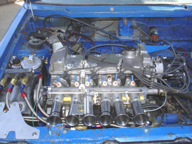
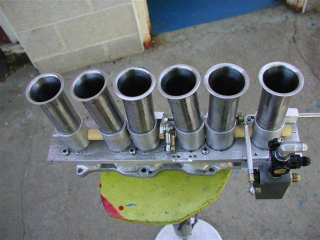
This is a completely fabricated from scratch Hilborn style mechanical fuel injection to fit a late 90's VW VR6 engine---will be about 178 to 183ci in race trim.
-This project is for a VW Rabbit pickup that Jesse Winders runs at the Bonneville salt flats and will need to run about 150MPH.
-This is a front wheel drive cross mounted engine.
-----------------------------------------------------------------------------
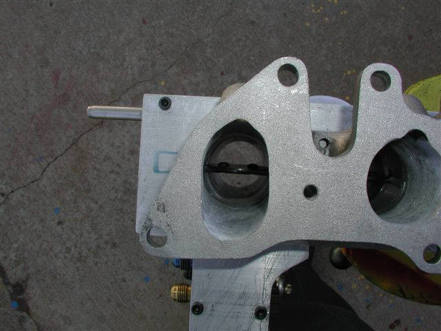
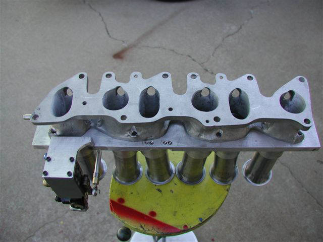
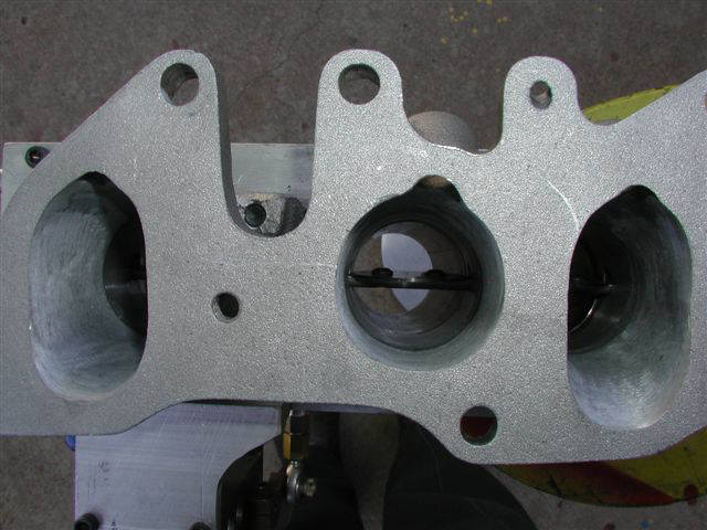
-The manifold was made from both ends of the stock manifold which was originally about 6" long and curved 90º upwards----and the port walls were so thin that I had to tig weld virtually everywhere on the outer surfaces to build up the wall thickness.
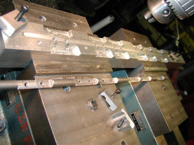
-For the injection assembly I started with the flat plate---bored and countersunk the holes to fit the position of the welded manifold------then I machined up 6 individual aluminum sleeves to press fit into these counter sunk holes.
-When I bored these holes I recorded the positions of my digital readout so I had an exact idea of where the throttle shafts would need to be machined flat for the throttle blades, and to be drilled & tapped for the throttle blade screws.
-Before I pressed the sleeves in I made a precise jig to machine the cross holes thru the 6 sleeves for the throttle shaft---and I had to bore the entrances of the two pairs of siamesed ports on an angle so I could tilt the stacks away from each other.
-I slid a piece of throttle shaft bar stock thru the 6 sleeves to align'm all real nice----and pulled'm into the main flange plate using 6 bolts and another plate placed on top of the sleeves.
-The throttle shaft holes are NOT cross drilled directly thru the center of the sleeves----these holes have to be precisely off to the side where the top of the throttle blades is to come UP----about a .040" offset.
-The intake valves of this particular engine are just under 1-9/16"-----and I chose to use 1-11/16" throttle blades that are common for Holley 750 & 780 cfm carburetors (just happened to have a supply of 1-11/16"throttle blades).
-To machine the long throttle shaft I had to first fabricate a jig & clamps so I could position & clamp the 5/16" bar stock----then set up the positions for drilling the throttle blade screws.
-I clamped the bar stock in place with 7 clamps---machined the 6 flat areas for the throttle blades--then drilled & tapped the shaft 12 places for throttle blade screws.
---------------------------------------------------------------------------------------------------------------------------------------
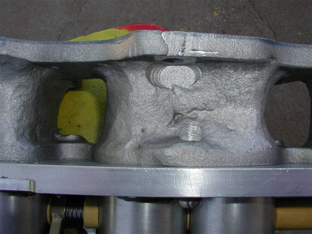
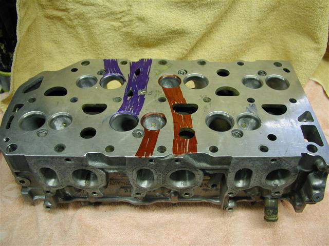
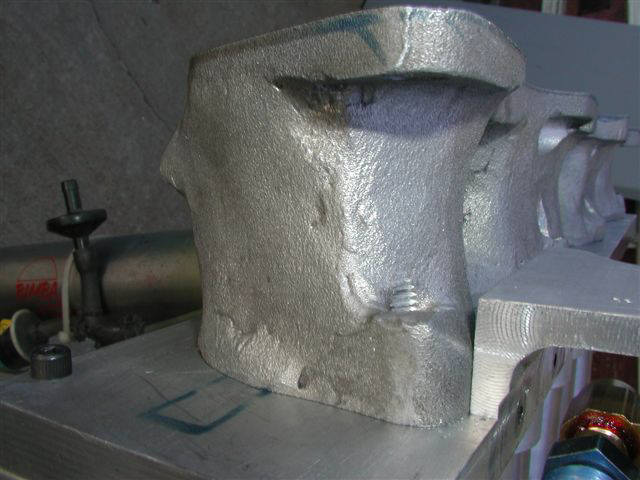
This engine is a little odd----sort of like a slightly wide 4 cylinder block but then has 3 cylinders bored on a 7.5º angle to one side---and the other 3 cylinders are bored 7.5º towards the other side---for a total of 15º.
-As the cylinder head photo shows there is no combustion chambers in the head---just has a 7.5º wedge angle above a flat top piston and then has some amount of dish built into the piston to get the compression ratio.
-Three of the intake ports are round at the manifold flange--and these go thru the head to the cylinders on the other side of the engine.
-The three oval ports are real short---just make quick down turn into the 3 cylinders closest to the manifold.
-The oval & round shapes are also used on the exhaust ports.
------------------------------------------------------------------------------------------------------------------------------------------
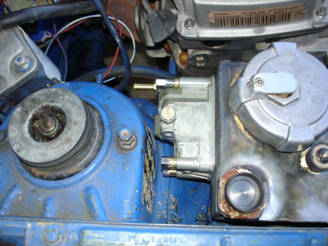
I built a small fuel tank shown mounted on the passengers side of the engine----with one Holley float bowl to control the incoming fuel that is pumped forward from the stock tank with an electric pump.
-This tank holds about 1-3/4 gallons---and it is mounted with rubber grommets to diminish some of the vibrations that may be caused by the engine being mounted solid in the chassis.
-The bottom of the tank has a welded piece of 2-1/2" tubing about 8" long hanging down close to the fuel pump---where a short #10 hose connects to the pump inlet.
--------------------------------------------------------------------------------------------------------------------------------------------
-A Hilborn "dash zero" pump, #4 Hilborn straight short aspirated nozzles,
and a Hilborn barrel valve with a #54 spool are the main components.
-The #4 nozzles represent .04gallons per minute when flowed at 30psi or about 15.2GPH at 30psi when using .760 specific gravity fuel.
-This #54 barrel valve spool is typically used on common V8 engines with gas or alcohol----and may prove to have too wide of a slot---which is listed at .200" wide in Kinslers literature.
-This width could possibly cause idle and part throttle to be too rich where the leakdown might need to be less than 8# and the part throttle secondary bypass may need to slightly less than 6.5#
-The barrel valve leakdown will set at 8% to start with---and could vary from maybe as low as 6.5% to as high as 14%----lower numbers being leaner at idle.
-The homemade leakdown tester uses a .043" restriction and testing is done with 100psi of air pressure.
-One Hilborn brass main jet bypass poppet can with the poppet set at about 2.5# for idle, main jet will be determined during flowtesting on my "wet flowbench" that I built years ago for testing mechanical fuel injections for sprint car engines.
-Main jet spring is .015" wire diameter, .315" OD, 1.385" free length, 9-1/2 coils.
-idle pressure is 2.5# with no shims but with the normal jet in place.
-expecting the main jet range to be .110" to .140" and a .120" jet will be used to start with.
-Another Hilborn brass secondary poppet can that controls part throttle fuel to the engine will likely have the poppet set somewhere between 6.5 to 16# of fuel pressure, so it will bypass all fuel above that setting up to about 40º of throttle opening.
-secondary spring is .0325" wire diameter. .360" OD, 1.100" free length, 13-1/4 coils.
-part throttle pressure range is 6.5# with no shim, 16# with .187" shim.
-each shim of .032" thickness will change the pressure 1.58#.
-initial starting point will be with no shim which is 6.5#.
-Another Hilborn brass hi-speed relief bypass poppet can controls the maximum system pressure---to be set at about 59.2# to start with---which will occur at about 6500rpm.
-A .310" diameter ball is installed inside the poppet---for the spring to push against where the force is pushing on the center of the poppet rather than from the machine step inside the inner perimeter---in an attempt to minimize the common leakage that happens prior to the desired pop off point.
-hi-speed relief spring is .041" wire diameter, .355" OD, 1.230" free length, 10-1/4 coils.
-pop off pressure range is 36# with no shim and 70# with a .187" shim.
-each .032" shim will change the pressure 5.8#.
-initial starting point will be 59.2# using a single .125" shim (about the same as four .032" shims, x 5.8 = 23.2 + 36 = 59.2#) and the .310" ball inside the poppet.
-These three brass poppet cans are shown mounted to a steel manifold that is shown rubber mounted to the top of the small fuel tank----and there is one additional hose that diverts all the fuel from the Hilborn pump to the tank whenever the 3 way fuel shutoff valve is closed.