-here are some photos of how I measure rocker rollout and roll back in on 14 degree Big Chief heads.
--------------------------------------------------------------
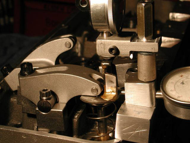
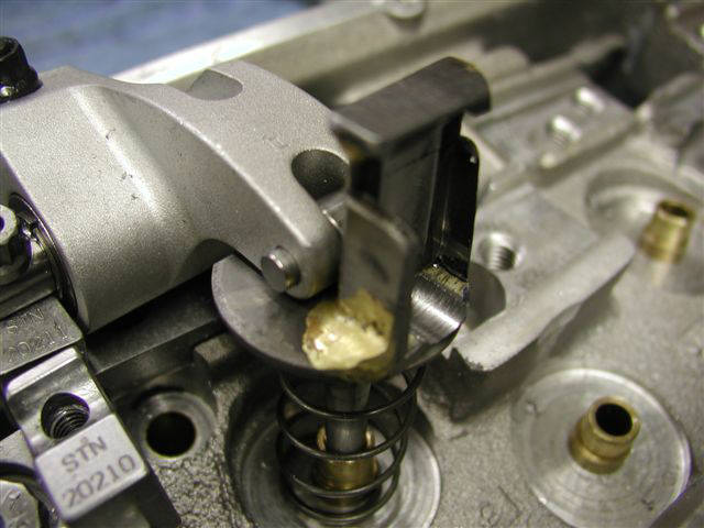
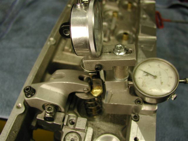
-The one part that slips onto the top of the valve is like a "C" washer with a vertical stand of about 1-1/4" in height brazed at a 90 degree angle to the washer.
-After it is brazed I machine it so that the roller tip can push against one side and the horizontal dial indicator is centered directly out from the crown of the roller wheel.
-the vertically mounted dial indicator tip presses down with a light spring to sort of hold the C washer stand from tipping backwards as the roller tip moves to an open position where the vertical indicator tip then tries to tip the C washer stand over backwards.
-It takes a little help by hand to hold the C washer stand in place when you start approaching about .700" lift and continue up to an inch in lift.
---------------------------------------------------------------------------------
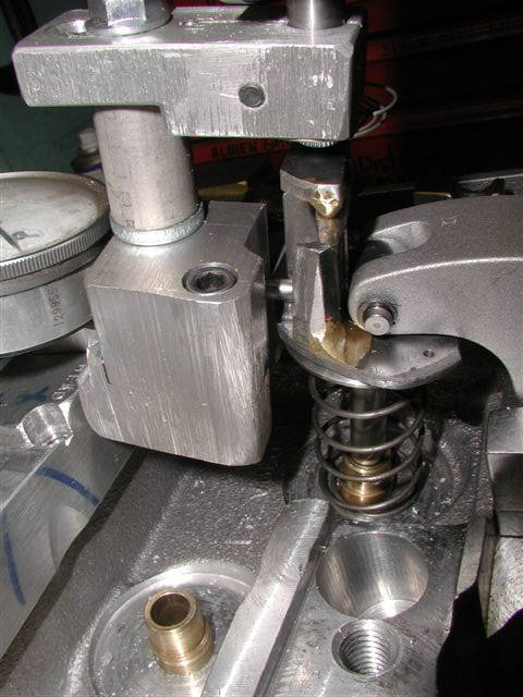
-this C washer stand is fairly complex to get it to fit in there and to get the indicator pressures to hold it in place---a little hard to get it machined nice and smooth etc.
----------------------------------------------------------------------------------
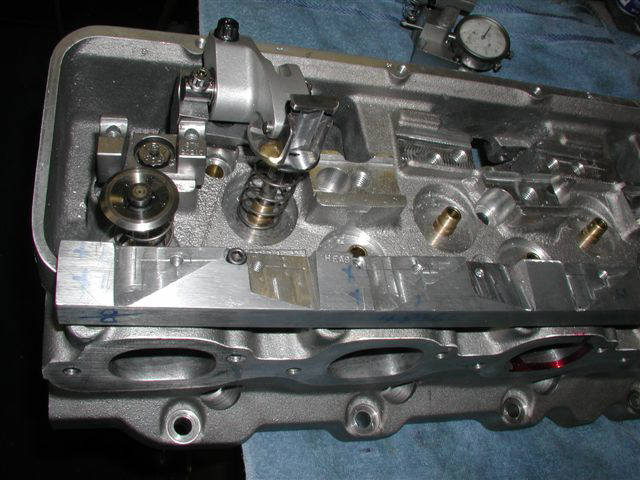
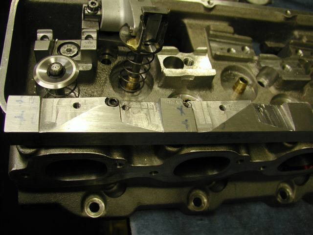
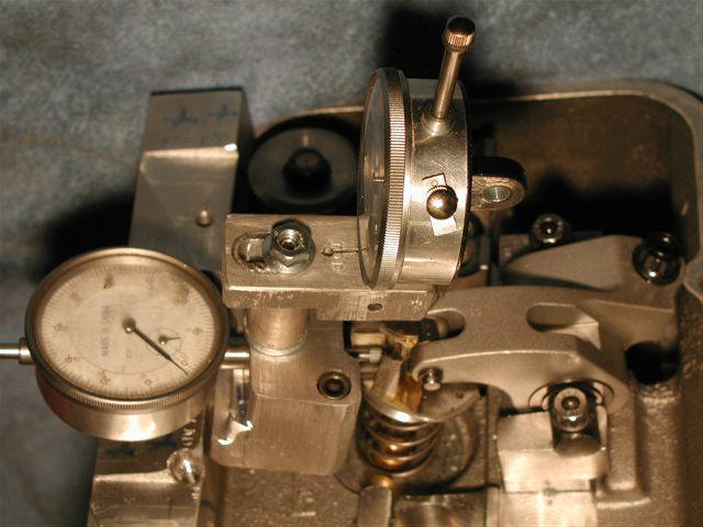
-the long bar was bolted to the valve cover rail---then the head was installed on my mill---tilted to the get the exhaust valve straight up---then I machined a slot to allow a mounting place for the dual dial indicator mount and a mounting hole was drilled and tapped.
-this was done four places so that all cylinders can be checked.
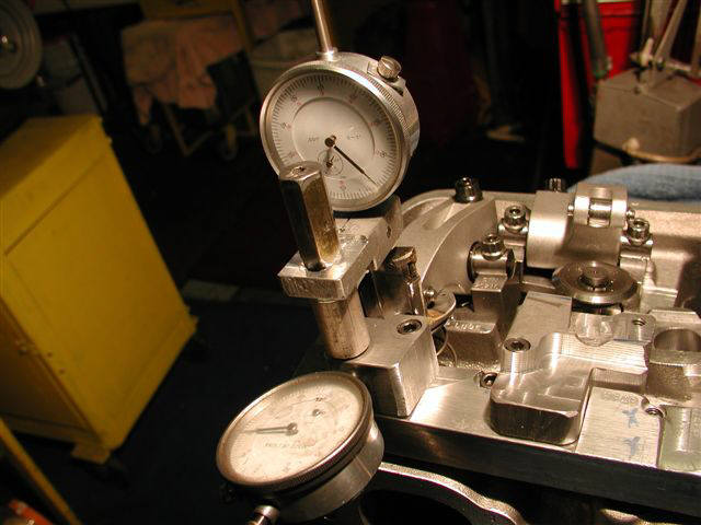
-After figuring out he mount and fabricating the mount and the C washer stand---getting to where I could actually check the exhaust----I then did the same procedure to get mounting positions on the long square bar for the intake.
-Then I had to make an intermediate attachment extension so I could use the same dual indicator mount to check the intake.
--------------------------------------------------------------------------------
-an example of what this shows me is:
1-I ran the valve open to 1.000" lift and recorded the roller tip roll starting with the horizontal dial indicator at zero with .100" preload----and with the vertical dial indicator at zero with 1.020" preload to measure the valve lift.
2-I opened the valve in .100" increments to 1.000" and checked and recorded the roll out and roll back in which started at zero and rolled out a maximum of about .093".
3-here is a chart of the results----all numbers are OUT from zero lift unless noted with a - sign
valve ---roll out/in---
lift int exh
.000" .000" .000"
.100" .031" .031"
.200" .054" .054"
.300" .071" .073"
.400" .083" .085"
.500" .089" .091"
.600" .090" .093"
.700" .080" .079"
.800" .050" .051"
.900" .028" .031"
1.000"
-.002"
.005"
4-This is with a light valve spring holding the valve closed and operating the rocker by hand---no shims were under the rocker stands.
5-Application will be using about a maximum net lift of .940" (raceready---after valve lash) on the intake and about .918" on the exhaust.
-cam is to be .520" intake lobe lift and .510" exhaust lobe lift with 1.85 rockers on both.
-The .940 x .918 lift numbers do NOT account for any lost of lift due to the elasticity of the metals.

Bill Jones' Photo Gallery Page 3
8 Photos showing Bill's Rocker Rollout Method