| 
                      
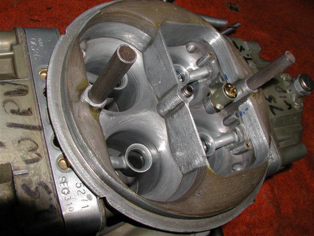
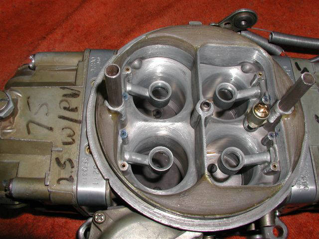
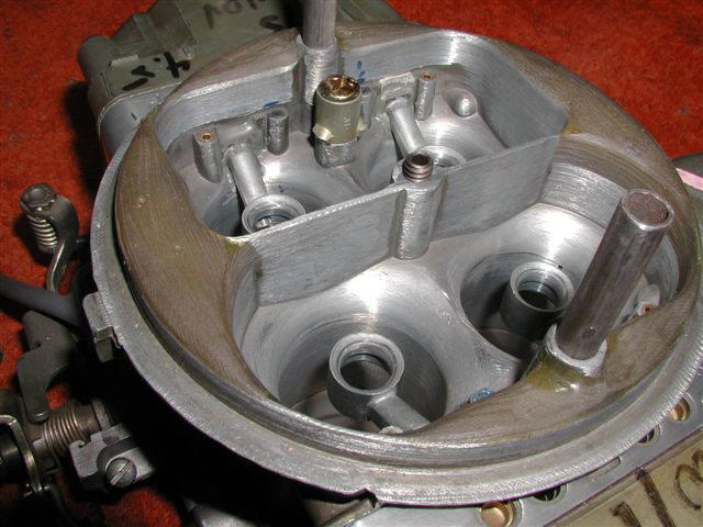
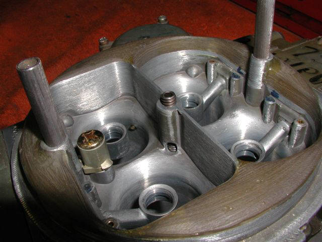
                        These 4 photos show some unknown brand clear epoxy that I used on this 780 carburetor to help the air get into the throats.


                          ---------------------------------------------------------


                          -One photo shows an angle drilled hole that intersects the air filter stud hole---this is drilled clear thru with a .265" drill bit----and the air filter stud is tapped way deep so that the air filter stud can be used to close off the angled hole.


                          -This allows an alterative method of getting some extra idle air without having to open the throttles or drill holes in the blades.


                          -The setscrew that's in the air filter stud hole is just to show how the lower sectionof the threads are to be closed off.


                          --------------------------------------------------------------


                          -the downleg boosters have the center holes enlarged and the underside of the booster has been machined with a step.


                          -JB Weld epoxy is applied at the booster to main body joint to help secure the boosters which have been swedged from the meter block side.


                          --------------------------------------------------------------------


                          -The original slanted top vent stacks have been discarded----then the holes have been reamed to 5/16" all the way down into the rectangular intersecting  vent.


                          -The bottom of the vent tubes shown are slotted and split so that the bottom 3/16" can be spread apart and locked within that rectangle vent cavity---so that there is NO possibility of the vent stacks ever coming out and down thru an engine.


                          -----------------------------------------------------------------------------------------------------------------


                          -I flowtested this carburetor during a series of modifications as follows:


                          TEST# / CFM


                           1-  687.9------initial test on a 2" open hole spacer, no airfilter, no choke blade or shaft but still had the choke horn.


                           2-  701.0-------only change was to a 2" tall 4 hole spacer with bottom blended to reduce turbulence.


                                  691.8    -same with a new 4" x 14" K&N on a dropped base with a normal chrome lid.


                                      662.9-same but exchanged to a dirty 3" x 14" K&N---1-9/16" from top of element to the carbs gasket circle.


                           (all subsequent tests shown below are based off the three sections of the #2 test but with each new modification)


                           3-  702.6-------removed the choke horn


                                  697.9    -4" K&N


                                      684.4-dirty 3" K&N filter.


                           4-  714.6-------installed correct length button head screws.


                                  712.0    -4" K&N


                                      692.9-dirty 3x14 filter.


                           5-  736.3-------epoxy the top area as show inb the photos.


                                  719.9    -4" K&N


                                      707.2-dirty 3" K&N


                           6-  752.8--------machine just the primary throttle shaft to .085" thick with correct length screws and fluff & buff the bores


                                   736.7    -4" K&N


                                       720.2-dirty 3" K&N


                           7-  755.2--------smooth up the secondary SHAFT and throttle bore slightly, no filter.


                           8-  761.2--------epoxy two corner areas of the secondary throttle bores that were for PCV use.


                           9-  774.0--------blend the 4 throttle bores of the main carburetor body, remove the casting lines at venturis & polish.


                          10-  779.7--------final-assembled race ready with careful attention at the main body to baseplate gasket.


                                    771.3   -4" K&N


                                       750.9-dirty 3" K&N


                          ----------------------------------------------------------------------------------------------------------------


                          11
                        
                        
                          .  768.4--------changed back to the 2" tall open hole spacer used in test #1


                                    754.5    -4" K&N


                                        739.0-dirty 3" K&N


                          -flowtesting the carburetor naked and with the two different filters shows that airfilters definetly cost flow---and that there is airflow to be had with attention to details.
                        
                         Bill Jones' Photo Gallery Page 4 Photos of Carburetor Entry Epoxy Prep |